Curve tracer christmas calendar 5 – Neon bulb

Todays post is going to be on those Neon bulbs often used as indicators. I had some 65V small neons to play with.

Did you know that a oscillator could be made with a neon bulb as the only active element? This must be the smallest component count oscillator there is?

Oscillation frequency should be close to 1/(2*pi*R*C). If you build this, please let me know how it works for you. The voltage needs to be approximately twice the neon bulb strike voltage, and R1 should preferably be around 1M ohms. Play around with the values and see what you get.

For the next days I think we will do some active components.

Curve tracer christmas calendar 1 – Diode

Starting today, the plan is to do a curve trace of one kind of device a day from now untill december 24. Some will just be a single trace, some will have explaination of one kind or another, and some may get full derrivation of the physics.

Today we are going to start off with a couple diodes. First out is the trusty 1N4148 diode:

As you can see, there is both the forward conduction at approximatly 0.7V, and the reverse breakdown at around 160V.

Looking more closely at the forward curve:

Forward curve of the 1N4148 diode

From this curve we can determine the slope and use the Shockley diode equation to get the diode parameters.

Doing a standard unnamed Germanium diode then the trace looks like this:

And for fun, here is a Mullard OA81 curve:

The looping is due to heating of the semiconductor junction.

End of a era

With the closure of Yahoo group, we are seeing a end of an era.  Roger KA7EXM just posted this to the EMRFD (Experimental Methods in RF Design) group:

Hello EMRFD Group Members,
As you have probably all realized, Yahoo is terminating it’s Group program.   It’s been a good thing for all sorts of interest groups including EMRFD.   That era has come to an end.    We thank Yahoo for their sponsoring efforts to enhance our education and enjoyment.
The sales of Experimental Methods in RF Design have slowly decreased and the book is approaching the end of publication.  EMRFD Yahoo group activity has slowed to a crawl, often with a month between postings.   We have also seen a change in the intensity and depth of the postings.   This led us to the conclusion that it is time to close the group.    It’s been a useful way for us to share a passion for our common interest in radio frequency electronics.
Free time is also becoming a challenge for both of us.   One of us (Roger, the Group founder) continues to work in the electronics industry with ever increasing responsibilities and fun.   That includes a smattering of RF work.   The other (Wes, presently the moderator) is retired, but still busy with some occasional experiments.
The simple way to shut things down would be to just let things lapse as Yahoo pulls the plug.   We didn’t want to do it this way, for the posting would then be lost.   Rather, the files, photos, and messages have been gathered and will be available at www.ka7exm.net/emrfd    It will take a while to get all of this data up, but it’s all downloaded.   Messages should be live by 27 October, photos and files will post in the coming weeks.
After a while, some of you may wish to resurrect the site, perhaps with a new name and new emphasis.   All of amateur radio is changing, so it only makes sense for the EMRFD group to evolve.
We would both like to thank all of you for sharing your thoughts and experimental results and designs.   The posts have been enlightening and stimulating.    Special thanks go to coauthors Rick Campbell, KK7B, and Bob Larkin, W7PUA.
73
Roger, KA7EXM, and Wes, W7ZOI.
EMRFD and the EMRFD group was a important part of my education.  The book and the e-mail group was a good place to learn electronic and RF design, starting with the basics, working up to large RF systems, amplifiers and transceivers.
The group did wind down in the last year. I believe part of that was due to several of the mentors leaving. I guess answering the same questions over and over again, without as much as a “thank you” takes a toll on those answering questions.
The book is showing its age. Several of the components used are EOL, not suprizing given that the book is closing on 15 years. A revision would be nice, but I don’t see that happening due to the authors age and limited time. Its sad, there is not many good RF engineering textbooks around.
Thank you to all of you making the ecosystem around the book. We had a great time!

Norwegian: Hytera DMR oppsett

This post is in Norwegian. It should be possible to get most of the gist from it if you don’t speak norwegian, or you could try one of the many other explaination of the setup available on the web.

DMR – Hytera korrekt oppsett.

For denne forklaringen brukes en Hytera PD985 med GPS. Alt som er forklart her gjelder for PD6, PD7 og PD9, samt det meste for de noe enklere PD4 og PD5 radioene til Hytera. For mobilstasjoner mangler det ett par små steg. Observer at PD4 og PD5 serie har egen utgave av programeringssoftware, samt andre nummer for firmware. Man kan annta at nye radioer fra forhandler leveres med en av de siste utgavene av firmware. For samtlige radioer er det helt nødvendig å ha tilgang på programeringskabel, selv om de fleste innstillingene kan settes via tastaturet. For å se bildene bedre, kan du høyreklikke på de, og velge “åpne bildet i ny fane”.

Last ned og innstaller siste utgave av Customer Programming Software (CPS) samt Subscriber Batch Upgrade (SBU) fra: https://www.hamdigitaal.nl/hytera-software-1/ og https://www.hamdigitaal.nl/hytera-firmware/

Dersom du ikke har en digital ID fra før, får du en her: https://register.ham-digital.org/

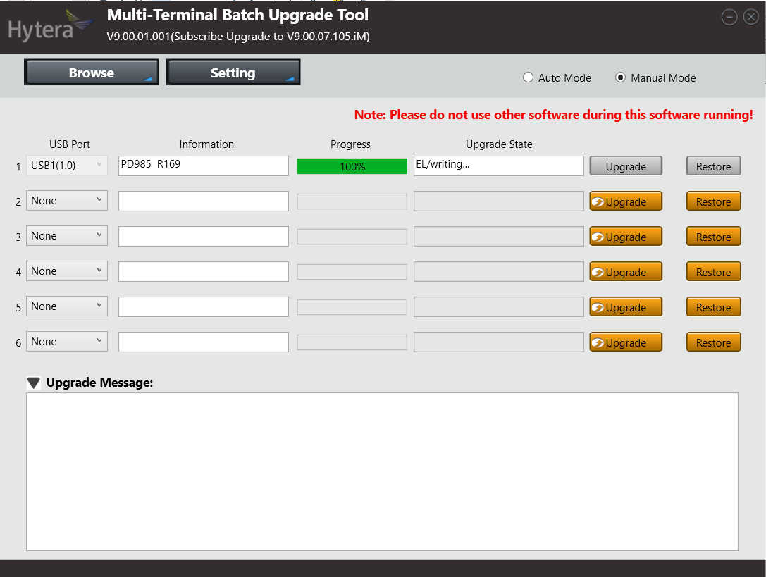
For å oppdatere firmwaren i radioen, kjør SBU. Dette er ett program som stiller store krav til tilgjengelig minne i radioen, slik at det er en fordel å re-starte PC’en før du starter det programmet. Koble radioen til PC, eventuell bryter på kabelen settes til DL, og sørg for at radioen er på før du starter programmet. Dersom radioen ikke går i oppdateringsmode automatisk, skru av radioen, hold inne orange «nødknapp» og PTT når du skrur på radioen. Oppdatering av firmware bør gjøres hver gang CPS oppdateres, ellers vil det være umulig å tilbakestille radioen til fabrikkinnstillinger. Dersom din radio har lavere firmware version enn V7.00 må det oppgraderes til V7 før det oppgraderes til siste versjon.

Steng SBU før CPS startes. Dersom det forsøkes å skrive til radioen med begge programmer aktive på PC, vil skrivingen feile. Sett bryteren på programeringskabelen tilbake til CPS før du forsøker å skrive til radioen.

hytera1

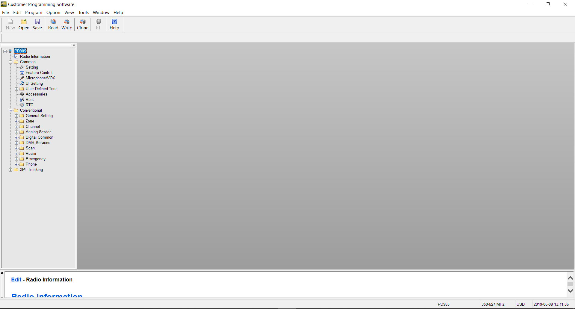
Når CPS er startet trykk «Read». Da lastes oppsettet i radioen inn i programmet. Utvid Common og Conventional. XPT Trunking er for større linkede systemer med flere repeatere koblet sammen på samme sted. Dette brukes ikke til amatørradio.

hytera2

Under Common – Settings:

Sett «Radio Alias» til ditt kallesignal + navn. I mitt tilfelle LA3PNA Thomas. Sett «Power-on Message Type» til «Radio Alias». Dersom du ønsker at det skal settes passord for å bruke, lese eller skrive til radioen, settes det her. Du kan velge norsk språk under «Language», vær obs på at enkelte oversettelser har noen feil.

hytera3

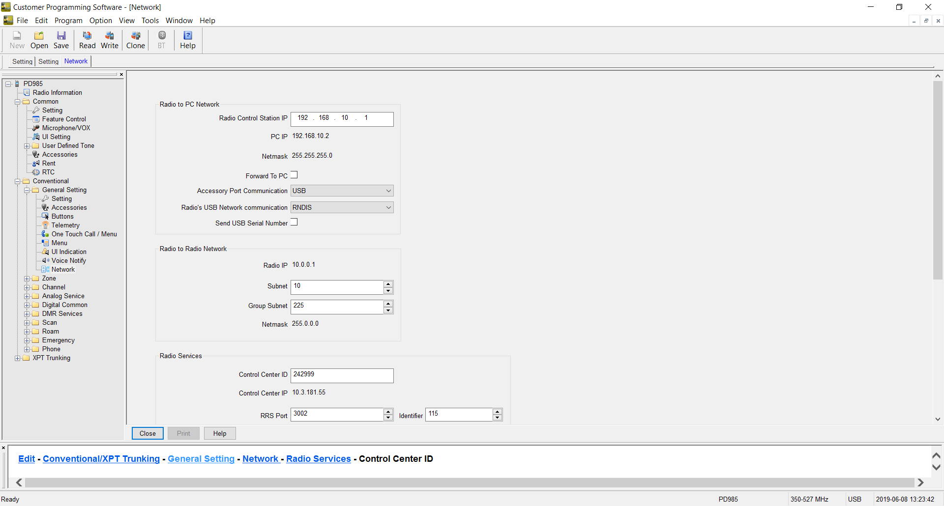
Under Conventional – General settings – Network:

Scroll ned til «Control Center ID» denne settes for Brandmeister i Norge til 242999. La alle andre innstillinger stå som de er.

hytera4

Under Conventional – Digital Common – Basic:

«Radio ID» settes til din digitale ID. Denne fikk du tilsendt på e-post når du registrerte deg som digital bruker.

Lengere ned, under «miscellaneous» settes «Data Bearer Service» til «Compressed IP»

Huk og ut «Auto Add Contacts» dersom du ønsker at de du hører på luften, automatisk skal legges til som kontakter i kontaktlisten.

hytera5

Det neste er å definere «kontakter». Dette er både de talegruppene vi ønsker å bruke, og personer vi sakker med. For enkelhets skyld vil jeg kun definere den nasjonale talegruppen 242, men det finnes mange andre som brukes. Lokalt bruker vi ID til en repeater (242650) slik at vi alltid kommer ut på den lokale repeateren, selv om vi skulle være på ett annet sted. Det er en fordel å se i Brandmeister for de lokale repeaterene du definerer. Både ID og at du velger rett tidsluke finner du i Brandmeister. Dersom du ikke har rett tidsluke, vil repeateren dynamisk linke til det tidsluke du bruker. Resultatet av dette er at du legger beslag på begge tidsluker, og hindrer en annen QSO som kunne gått samtidig.

Under Conventional – DMR Services – Contact:

Legg til «Nasjonal 242» som «Group call» og med Call ID «242»

Ut over dette trenger vi ikke å definere noen flere kontakter nå, vi kan definere de når vi legger til flere kanaler.

hytera6

Under Conventional – Channel – Digital Channel:

Velg «CH D1», og rediger denne slik at den passer med din lokale DMR repeater. Jeg har valgt å kalle min kanal LD3DV 242, siden dette er LD3DV, i talegruppe 242.

Start med å sette korrekt frekvens. Dette er nødvendig for å få huket ut «Multisite IP Connect».

Sett RX group list til «None», TX contact name til «Nasjonal 242», «Location Info Revert Channel» og «RSS Revert Channel» settes til «Selected». «Emergency system» og «Phone system» settes til «None». «Power level» settes til det som måtte passe. «TX admit» settes til «Channel Free». «TX time out time» settes til ett passende nivå. 60 sekunder er ofte litt lite for amatørtrafikk.

hytera7

hytera8

Under Conventional – Zone – Zone1:

Zone er en utvidelse av kanallisten hvor man kan ha en zone for repeatere, en for simplex osv.

I dette tilfellet velger vi bare å fjerne alle kanalene vi ikke har redigert, så «LD3DV 242 står tilbake alene.

[9]

Dersom du nå laster opp denne konfigurasjonen til radioen, skal du kunne prøve den mot den nasjonale talegruppen.

Samme prosedyre med innlegging av kontakt, kanal, og så i zone brukes for alle andre kanaler du ønsker å ha i radioen. Analoge kanaler kan fint blandes med digitale i samme zone.

hytera9

For radioer med innebygget GPS:

For å få en knapp som sender GPS posisjon, velg Conventional – General Settings – Button, og sett «SK2 long» til «GPS Report».

Velg videre Conventional – General settings – Accessories og under «GPS trigger» huk av «Button». Her har du og muligheten til å sette at den automatisk sender posisjonsrapport etter en gitt tid eller avstand. Under «voice w/Location» huk av både «Voice w/Location» og «PTT». Da sendes posisjonen automatisk når du trykker inn PTT.

Tillegg 05/02-24: Dersom ikke DPRS (APRS) fungerer, skru av GPS data compression under General-> Settings -> Accesories

Installing DokuWiki on Synology

Since it seems a common problem to get DokuWiki to work on Synology NAS, here are some tips:

  1. Before installing go to: “Web Station” and “PHP Settings” then select your PHP version profile.  Under extensions, add “mcrypt” and “openSSL”.
  2. Install DocuWiki.
  3. Run DocuWiki installation setup, make sure to set your needed parameters here.

If you have installed DocuWiki, but not gotten it to work, make sure you remove it in “Packet Center” before adding the extensions.

Happy Wiki’ing.

Cadlab.io

Some time back, I was contacted by someone from cadlab.io, asking if I would like to try it out.

Cadlab.io is a way of providing git with a extension to show Cadsoft Eagle files.

unnamed

As the gif shows, there are ways of comparing the different commits, and showing both PCB layout and schematics.

There is both a free version, and a paid one with private repositories.  It’s a great tool for developing hardware, I just wish that github and the like would adopt it and incorporate it into their platform.

From what I have been able to get out of cadlab, KICAD files should be supported by the end of the year, and Altium may come after that.  For the record, I’m not receiving anything for writing this,  but its appearing as a new, useful tool for making hardware.

Si5351 VFO sketches

Back when Etherkit did come out with its Si5351 boards, I wrote some sketches to use these as VFO’s.  These sketches have been floating around the internet, without being collected at a single place, so thats going to change, in hope that it will reduce the repeating e-mails a bit.

Both sketches work as a basic VFO. It starts at a given frequency, and there is not implemented a method of changing bands. This can be easily added by someone with a little programming experience.  All of these sketches requires NT7S Si5351 library. Please support his development by buying a board.

The encoder used is a regular quadrature encoder (not Graycode, altough using a stepper motor as a graycode encoder should be investigated). There needs to be a couple debouncing capacitors (100nF) over each of the leads from encoder to ground. This should go as close to the encoder as possible. In addition, you may want to add a 22Ω resistor in series with the A and B leads, and another 100nF at the microcontroller side.

There is a RX/TX pin. Put this pin LOW for RX or the VFO will not tune. This is a tune inhibit function, and can be used for locking the tuning while TX.

The sketches are made to work on both AtMega328 and AtMega32U4 boards. There is some preprosessor switches to decide between those 2. If you use a different board, you may need to use a different set of interrupt pins, and some other preprosessor switches.

All of these sketches are provided free of charge, as is, for use by experimenters in non-comercial ways. There is no warranty nor support, altough I may answer some questions…

There exists 2 kinds of versions of the sketch depending on what display you want to use:

16×2 LCD  Display

This is the most common one.

51jy8enJluL


/*
Si5351 VFO
By LA3PNA 27 March 2015
Modified 14 February 2017
Modified 28 November 2018
This code is licenced with GNU GPL v2. Please read: https://www.gnu.org/licenses/old-licenses/gpl-2.0.html
This version uses the new version (v2) of the Si5351 library from NT7S.
see: http://arduino.cc/en/Reference/AttachInterrupt for what pins that have interrupts.
UNO and 328 boards: Encoder on pin 2 and 3. Center pin to GND.
Leonardo: Encoder on pin 0 and 1. Center pin to GND.
100nF from each of the encoder pins to gnd is used to debounce
The pushbutton goes to pin 4 to set the tuning rate.
Pin 5 is the RX/TX pin. Put this pin LOW for RX, open or high for TX.
Single transistor switch to +RX will work.
VFO will NOT tune in TX.
LCD connections:
* LCD RS pin to digital pin 12
* LCD Enable pin to digital pin 11
* LCD D4 pin to digital pin 10
* LCD D5 pin to digital pin 9
* LCD D6 pin to digital pin 8
* LCD D7 pin to digital pin 7
* LCD R/W pin to ground
* LCD VSS pin to ground
* LCD VCC pin to 5V
* 10K pot:
* ends to +5V and ground
* wiper to LCD VO pin (pin 3)
IF frequency is positive for sum product (IF = RF + LO) and negative for diff (IF = RF – LO)
VFO signal output on CLK0, BFO signal on CLK2
ToDo:
*
*/
volatile uint64_t frequency = 7100000; // This will be the frequency it always starts on.
long iffreq = 0; // set the IF frequency in Hz.
long freqstep[] = {50, 100, 500, 1000, 5000, 10000}; // set this to your wanted tuning rate in Hz.
int corr = 10; // this is the correction factor for the Si5351, use calibration sketch to find value.
unsigned int lastReportedPos = 1; // change management
static boolean rotating = false; // debounce management
#include <si5351.h>
#include "Wire.h"
#include <LiquidCrystal.h>
Si5351 si5351;
// interrupt service routine vars
boolean A_set = false;
boolean B_set = false;
LiquidCrystal lcd(12, 11, 10, 9, 8, 7);
#if defined(__AVR_ATmega32U4__) || defined(__AVR_ATmega16U4__)
int encoderPinA = 0; // rigth
int encoderPinB = 1; // left
#endif
#if defined(__AVR_ATmega328P__) || defined(__AVR_ATmega168__)
int encoderPinA = 2; // rigth
int encoderPinB = 3; // left
#endif
int inData;
bool tx;
int txpin = 5;
int freqsteps = 1;
int stepbutton = 4;
#define arraylength (sizeof(freqstep) / sizeof(freqstep[0]))
void setup() {
pinMode(encoderPinA, INPUT);
pinMode(encoderPinB, INPUT);
//pinMode(clearButton, INPUT);
pinMode(stepbutton, INPUT);
pinMode(txpin, INPUT);
digitalWrite(txpin, HIGH);
// turn on pullup resistors
digitalWrite(encoderPinA, HIGH);
digitalWrite(encoderPinB, HIGH);
digitalWrite(stepbutton, HIGH);
#if defined(__AVR_ATmega32U4__) || defined(__AVR_ATmega16U4__)
//Code in here will only be compiled if an Arduino Leonardo is used.
// encoder pin on interrupt 0 (pin 0)
attachInterrupt(1, doEncoderA, CHANGE);
// encoder pin on interrupt 1 (pin 1)
attachInterrupt(0, doEncoderB, CHANGE);
#endif
#if defined(__AVR_ATmega328P__) || defined(__AVR_ATmega168__)
//Code in here will only be compiled if an Arduino Uno (or older) is used.
attachInterrupt(0, doEncoderA, CHANGE);
// encoder pin on interrupt 1 (pin 1)
attachInterrupt(1, doEncoderB, CHANGE);
#endif
si5351.init(SI5351_CRYSTAL_LOAD_8PF, 0, corr);
lcd.begin(16, 2);
lcd.print("Si5351 VFO");
Serial.begin(9600);
delay(2000);
si5351.set_freq(iffreq * 100ULL, SI5351_CLK2);
}
// main loop, work is done by interrupt service routines, this one only prints stuff
void loop() {
tx = digitalRead(txpin);
rotating = true; // reset the debouncer
if ( lastReportedPos != frequency) {
lastReportedPos = frequency;
lcd.setCursor(0, 1);
lcd.print(" ");
lcd.print((long)frequency);
si5351.set_freq((frequency + iffreq) * 100ULL, SI5351_CLK0);
}
delay(50);
if (Serial.available() > 0) // see if incoming serial data:
{
inData = Serial.read(); // read oldest byte in serial buffer:
}
if (inData == 'F') {
frequency = Serial.parseInt();
inData = 0;
}
if (digitalRead(stepbutton) == LOW ) {
delay(150); // delay to debounce
if (digitalRead(stepbutton) == LOW ) {
freqsteps = freqsteps + 1;
Serial.print(freqstep[freqsteps – 1]);
Serial.print(" ");
Serial.print(freqsteps);
Serial.print(" ");
Serial.println(sizeof(freqstep));
if (freqsteps > arraylength – 1 ) {
freqsteps = 0;
}
delay(1000); //delay to avoid many steps at one
}
}
}
// Interrupt on A changing state
void doEncoderA() {
// debounce
if ( rotating ) delay (1); // wait a little until the bouncing is done
// Test transition, did things really change?
if ( digitalRead(encoderPinA) != A_set ) { // debounce once more
A_set = !A_set;
// adjust counter + if A leads B
if ( A_set && !B_set ) {
if (!tx) {
frequency += freqstep[freqsteps]; // hehre is the amount to increase the freq
}
rotating = false; // no more debouncing until loop() hits again
}
}
}
// Interrupt on B changing state, same as A above
void doEncoderB() {
if ( rotating ) delay (1);
if ( digitalRead(encoderPinB) != B_set ) {
B_set = !B_set;
// adjust counter – 1 if B leads A
if ( B_set && !A_set ) {
if (!tx) {
frequency -= freqstep[freqsteps]; // here is the amount to decrease the freq
}
rotating = false;
}
}
}

view raw

Si5351_VFO

hosted with ❤ by GitHub


If you want to use this with I2C 1602 modules:

There is currently no way of using it directly on the Si5351 sketches I have written. I would assume that the modifications to the regular LCD display sketch would not be too hard to do.
Looking at this page:
https://www.sunfounder.com/learn/sensor-kit-v2-0-for-arduino/lesson-1-display-by-i2c-lcd1602-sensor-kit-v2-0-for-arduino.html
Down load the LCD library shown there, you should then be able to
replace the line 58 #include <LiquidCrystal.h> with #include
<LiquidCrystal_I2C.h> and line 64 LiquidCrystal lcd(12, 11, 10, 9, 8,
7); with LiquidCrystal_I2C lcd(0x27,16,2);
I have not tried it, but it should be one way of using those 16×2 I2C displays.


OLED display

There is some nice, small OLEDS around for $3 or so that can be used with a graphics library called U8glib: https://github.com/olikraus/u8glib

CBRj6jXWsAABwJQ


/*
VFO program for Si5351
Using I2C LCD from:
http://www.amazon.com/Huhushop-TM-Serial-Display-Arduino/dp/B00JM88A94/
Si5351 library from NT7S.
Uses the updated version of the library (master).
Updated with the format_freq routine from Tom AK2B
This code is licenced with GNU GPL v2. Please read: https://www.gnu.org/licenses/old-licenses/gpl-2.0.html
Display library is avaible from:
https://code.google.com/p/u8glib/
UNO and 328 boards: Encoder on pin 2 and 3. Center pin to GND.
Leonardo: Encoder on pin 0 and 1. Center pin to GND.
100nF from each of the encoder pins to gnd is used to debounce
The pushbutton goes to pin 6 to set the tuning rate.
Pin 7 is the RX/TX pin. Put this pin LOW for RX, open or high for TX.
Single transistor switch to +RX will work.
VFO will NOT tune in TX.
In serial monitor, you can send "F"+frequency to set frequency. Ex: "F7063000"
IF frequency is positive for sum product (IF = RF + LO) and negative for diff (IF = RF – LO)
VFO signal output on CLK0, BFO signal on CLK2
TODO:
* Write own OLED i2c library with optimizing for text to reduce size of compiled program.
*Add variable tuning resolution
*/
volatile unsigned long frequency = 144400000; // This will be the frequency it always starts on.
long freqstep[] = {50, 100, 500, 1000, 5000, 10000}; // set this to your wanted tuning rate in Hz.
int corr = 120; // this is the correction factor for the Si5351, use calibration sketch to find value.
long iffreq = 0; // set the IF frequency in Hz.
#include "U8glib.h"
U8GLIB_SSD1306_128X32 u8g(U8G_I2C_OPT_NONE); // I2C / TWI
String str;
char b[8];
int inData;
String displayFreq;
boolean A_set = false;
boolean B_set = false;
unsigned int lastReportedPos = 1; // change management
static boolean rotating = false; // debounce management
#include <si5351.h>
#include "Wire.h"
Si5351 si5351;
// int encoderPinA ;
//int encoderPinB;
#if defined(__AVR_ATmega32U4__) || defined(__AVR_ATmega16U4__)
int encoderPinA = 0;
int encoderPinB = 1;
#endif
#if defined(__AVR_ATmega328P__) || defined(__AVR_ATmega168__)
int encoderPinA = 2;
int encoderPinB = 3;
#endif
bool tx;
int txpin = 7;
int freqsteps = 1;
int bandbutton = 6;
#define arraylength (sizeof(freqstep) / sizeof(freqstep[0]))
void setup()
{
// set the encoder to inputs
pinMode(encoderPinA, INPUT);
pinMode(encoderPinB, INPUT);
pinMode(txpin, INPUT);
pinMode(bandbutton, INPUT);
// turn on pullup resistors
digitalWrite(encoderPinA, HIGH);
digitalWrite(encoderPinB, HIGH);
digitalWrite(txpin, HIGH);
digitalWrite(bandbutton, HIGH );
u8g.setFont(u8g_font_courB12);
Serial.begin(9600);
// Initialize the Si5351
// Change the 2nd parameter in init if using a ref osc other
// than 25 MHz
si5351.init(SI5351_CRYSTAL_LOAD_8PF, 0, corr);
si5351.drive_strength(SI5351_CLK0, SI5351_DRIVE_4MA);
si5351.drive_strength(SI5351_CLK2, SI5351_DRIVE_4MA);
// assign default color value
if ( u8g.getMode() == U8G_MODE_R3G3B2 ) {
u8g.setColorIndex(255); // white
}
else if ( u8g.getMode() == U8G_MODE_GRAY2BIT ) {
u8g.setColorIndex(3); // max intensity
}
else if ( u8g.getMode() == U8G_MODE_BW ) {
u8g.setColorIndex(1); // pixel on
}
else if ( u8g.getMode() == U8G_MODE_HICOLOR ) {
u8g.setHiColorByRGB(255, 255, 255);
}
#if defined(__AVR_ATmega32U4__) || defined(__AVR_ATmega16U4__)
encoderPinA = 0;
encoderPinB = 1;
//Code in here will only be compiled if an Arduino Leonardo is used.
// encoder pin on interrupt 2 (pin 0)
attachInterrupt(2, doEncoderA, CHANGE);
// encoder pin on interrupt 3 (pin 1)
attachInterrupt(3, doEncoderB, CHANGE);
#endif
#if defined(__AVR_ATmega328P__) || defined(__AVR_ATmega168__)
encoderPinA = 2;
encoderPinB = 3;
//Code in here will only be compiled if an Arduino Uno (or older) is used.
attachInterrupt(0, doEncoderA, CHANGE);
// encoder pin on interrupt 1 (pin 1)
attachInterrupt(1, doEncoderB, CHANGE);
#endif
si5351.set_freq((iffreq) * 100ULL, SI5351_CLK2);
}
void loop()
{
tx = digitalRead(txpin);
rotating = true; // reset the debouncer
if ( lastReportedPos != frequency) {
lastReportedPos = frequency;
// Serial.print(frequency); // unncomment this to output frequency on change.
si5351.set_freq((frequency + iffreq) * 100ULL, SI5351_CLK0);
}
if (digitalRead(bandbutton) == LOW ) {
delay(150); // delay to debounce
if (digitalRead(bandbutton) == LOW ) {
freqsteps = freqsteps + 1;
Serial.print(freqstep[freqsteps – 1]);
Serial.print(" ");
Serial.print(freqsteps);
Serial.print(" ");
Serial.println(sizeof(freqstep));
if (freqsteps > arraylength – 1 ) {
freqsteps = 0;
}
delay(1000); //delay to avoid many steps at one
}
}
format_freq();
// rebuild the picture after some delay
delay(50);
if (Serial.available() > 0) // see if incoming serial data:
{
inData = Serial.read(); // read oldest byte in serial buffer:
}
if (inData == 'F') {
frequency = Serial.parseInt();
inData = 0;
}
}
// Interrupt on A changing state
void doEncoderA() {
// debounce
if ( rotating ) delay (1); // wait a little until the bouncing is done
// Test transition, did things really change?
if ( digitalRead(encoderPinA) != A_set ) { // debounce once more
A_set = !A_set;
// adjust counter + if A leads B
if ( A_set && !B_set ) {
if (!tx) {
frequency += freqstep[freqsteps]; // hehre is the amount to increase the freq
}
rotating = false; // no more debouncing until loop() hits again
}
}
}
// Interrupt on B changing state, same as A above
void doEncoderB() {
if ( rotating ) delay (1);
if ( digitalRead(encoderPinB) != B_set ) {
B_set = !B_set;
// adjust counter – 1 if B leads A
if ( B_set && !A_set ) {
if (!tx) {
frequency -= freqstep[freqsteps]; // here is the amount to decrease the freq
}
rotating = false;
}
}
}
void format_freq() {
u8g.firstPage();
do {
u8g.setPrintPos(0,15);
uint16_t f, g;
f = frequency / 1000000;
if (f < 10)
u8g.print(' ');
u8g.print(f);
u8g.print('.');
f = (frequency % 1000000) / 1000;
if (f < 100)
u8g.print('0');
if (f < 10)
u8g.print('0');
u8g.print(f);
u8g.print('.');
f = frequency % 1000;
if (f < 100)
u8g.print('0');
if (f < 10)
u8g.print('0');
u8g.print(f);
u8g.setPrintPos(80,32);
u8g.println(freqstep[freqsteps]);
if (tx)
{
u8g.drawStr( 110, 15, "TX" );
}
//draw();
} while ( u8g.nextPage() );
}

view raw

Si5351_i2c_mod

hosted with ❤ by GitHub

This version supports both Arduino Uno with ATMega 328, and Arduino Leonardo with ATMega 32U4.

If you do use this code, please send me a mention, either in the comment or on twitter so other can see what you are doing.