Observe that Mitsubishi has EOL’ed (End Of Life) most of their MOSFET range as of Jan 1. 2019
The last 15 years there have been a large development in MOS hybrid preformance, combined with a reduction in price, making these hybrid amplifiers quite a reasonable choice for a power amplifier in a VHF or UHF transceiver.
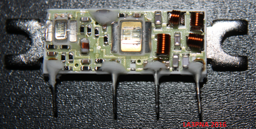
This hybrid is the Mitsubishi RA07H0608M made for the 60-88MHz range. I have been using these for experiments in the 70MHz band with both linear modes and FM. This hybrid should work on 50MHz, but determining the optimal bias point for linear would require the ability to do 2-tone testing.
I managed to burn out one of the amplifier modules due to self oscilations, and wanted to do some reverse engineering of what’s in the hybrid.
This hybrid is a thick film hybrid with 2 MOSFET dies, one for the PA and one for the driver in addition to biasing and impedance maching components. The white goop is probably non-acidic sillicone used to attach the plastic casing to the substrate and cooling tab.
The driver amplifier is a vertical MOS die, approximately 1mm x 2mm in size and with 2 bond wires to the base, and 3 to the drain.
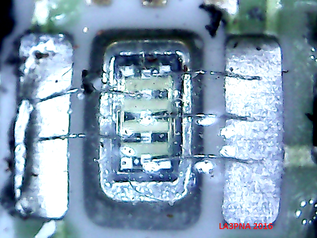
The PA transistor is a fairly large vertical MOS device, with 2 clearly visible trenches and several bonding wires on the drain. This is to reduce the inductance in the bonding wire and carry enough current. The die is quite large, approx 3mm x 3mm in size. There are some interconnections on the top of the die, but due to the passivation and sillicone around the die, its difficult to see the connections clearly.
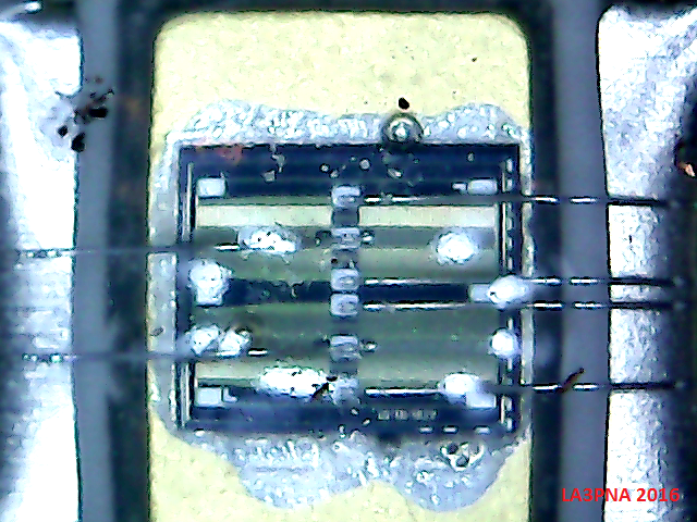
A interesting thing is how one pass wires over antother. The hybrid consists of a ceramic base (called substrate), with a groundplane on the backside that are bonded to the cooling tab. Traces is then put on the top of the ceramic substrate and fused together by firing. In order to make a wire pass over another, the bottom wire is laid down and fired (heated in a furnace to a given temperature), then a isolating layer is laid down and fired before the other trace is laid down and fired. This is done because there is only one layer avaible to put traces on, and having extra wire connections to the hybrid is expensive. The opague isolator as shown are probably BeO, although the datasheet don’t mention that there is BeO in the device. BeO dust is toxic.
The traces shown here is the bias line to the PA FET passing over the drain supply to the driver FET.
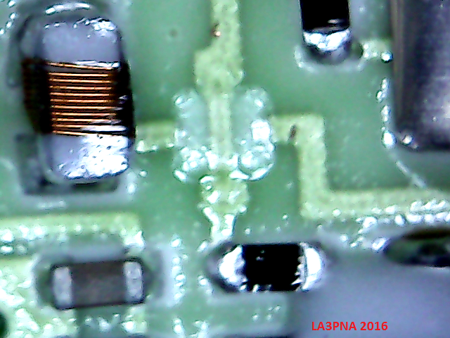
Another interesting thing about this hybrids are the extensive use of 0402 and 0603 resistors and capacitors. With thick film hybrids, its quite possible to put the resistors directly on the substrate. A reason to not do that in a amplifier like this may be that the resistors will have a termal gradient and that the resistors would require expensive laser trimming. High value capacitors like those used for decoupling are hard to make on a hybrid like this, so soldering in regular SMD components, and even electrolytics some times.
The PA FET has negative feedback to reduce gain and improve stability, while I could not see any for the driver. There seems to be some damage to my module there, could I have blown that off the hybrid? The increase in drive level by adding some light feedback to the driver may be worth a experiment.
The output and input matching looks to be of the lowpass kind, and on the output there are some harmonic supression. The RF design here clearly outperforms the mechanical and cooling. Interfacing these modules into circuits that once held older bipolar hybrids may not be straigth forward. There is a lot of gain to several GHz avaible in the FET’s and the grounding needs to be good to avoid oscillations.
Overall, the reverse engineering of these modules were quite interesting. A interesting thing to do may be to trace out the shcematic, although it should look like most any of the other modules available. Curve tracing the FET could be interesting to determine their parameters.
